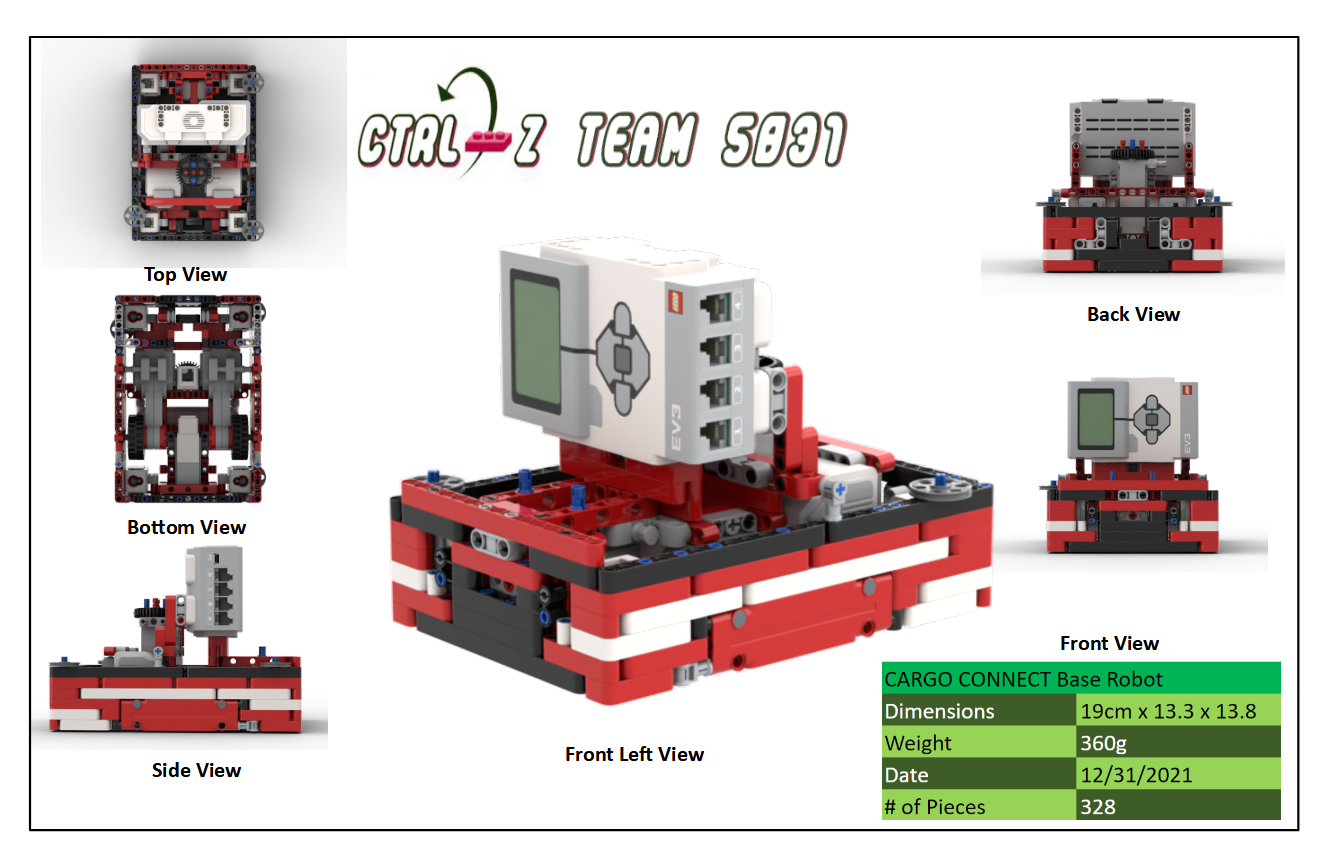
When designing our base robot, we established criteria at the outset, such as desired footprint, height, balance, drive train, sensors to be used, user interface, etc. to arrive at a working prototype. We also strived to design and build a robust base robot, which features a frame around the chassis to provide structural rigidity as well as means to square up against walls and mission models. When we design attachments, we keep in mind that these attachments need to be robust, easy to install and remove, and both passive and multi-purpose whenever possible. From testing the prototype base robot and the attachments, we revised our work to combine and speed up missions and increase repeatability to achieve maximum efficiency.
Our robot is very robust and compact with a frame for strength and an easier way to drop in attachments. We use four color sensors, well shielded from ambient light. Our robot has two small trailing wheels at the back of the frame, which are steering neutral, and small drive wheels. These small wheels allow for more accurate movements as they decrease the effect of error associated with the drive motor rotation sensors. However, we sacrifice some speed due to our small drive wheels. Our robot also has three guide wheels, on the sides of the robot, to follow the wall.
We have found that the move functions provided by the EV3 suite are unreliable. Although they have a built in PID feature, they still do not move the robot in a straight line. To test this, we set a designated starting spot for the robot and then we ran it until it hit the wall on the other side of the table. We repeated this dozens of times and found that each time it would end up in a different spot on the other side of the table. Each time it would be up to an inch away from the previous run. Then, we made our own error-corrected movement function (which you can read about in the programming section of this website). We conducted the same experiment using our block and found that there was much less error and the robot would consistently end up in the same position on the table.
| Name of Attachment | Description | Picture |
|---|---|---|
| Z Forklift, Arm 2, Z Weight, Z Package | In the first zone, our robot uses these attachments to latch the truck to the bridge and lower both bridge decks and train tracks. Then it delivers the package and uses the forklift to retrieve the blue and green containers and bring them to Home. |
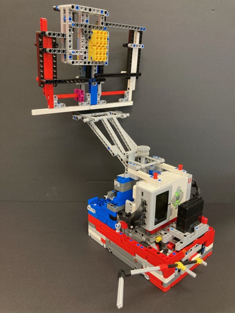
|
| Big Fancy Arm, Little Arm | In the second zone, our robot uses these attachments to switch the engine from diesel to electric, lower the cargo plane door and drag its container into the gray circle, and push the blue-hinged container to Home. |
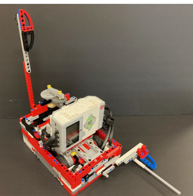
|
| Geary, Arm 1, Z Arm | In the last zone, our robot pushes the hinged blue container to the gray circle, drags the airplane and the truck to their destinations, unloads the cargo ship, separates the food package from the helicopter, pushes the train to the latch at the end of the tracks, balances the cargo on the ship’s west deck, and knocks down the yellow accident-avoidance panel. |  |